Rollover & Click on the highlighted sections in the image below for more details.
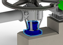
The bottom bearing supports the weight of the centershaft as well as the rabble arms and teeth. The bottom bearing is typically a button bearing in an oil bath, however, roller bearings are not uncommon. Industrial Furnace can supply new bottom bearing assemblies or parts for any MHF.
Click on the thumbnails below for additional information
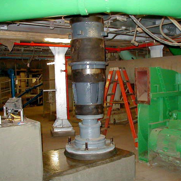
This is a bottom bearing being installed underneath the MHF
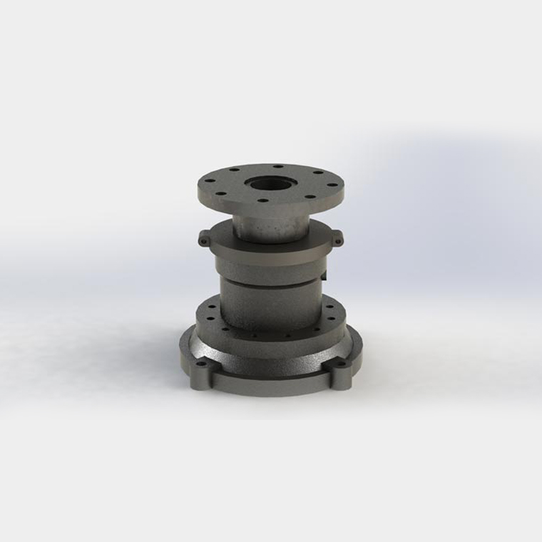
This is a 3D rendered image of a bottom bearing. The bottom holes secure the bearing to the pedestal, and the top flange connects to the lower shaft section of the centershaft.
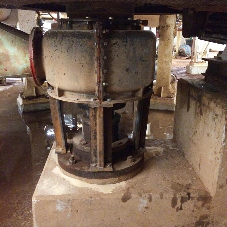
This is a bottom bearing installed on an MHF. Also shown is the cooling air housing where ambient air is injected to cool the centershaft and arms.
-

-

-

-

‹›
< back to main image
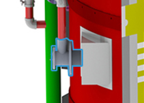
The combustion system is often the heart of the multiple hearth furnace. The burners provide the energy to bring the furnace up to process temperature, and in many cases, provide the energy to create the desired reactions inside the furnace. Industrial Furnace uses components from many different manufacturers to custom build the combustion system. We have worked with burner companies to develop a burner specifically for the MHF, however, we can use the more traditional burners as well. Our combustion system is controlled with all the required flame safety monitoring, and we build our systems to comply with NFPA and any other governing standards.
Click on the thumbnails below for additional information
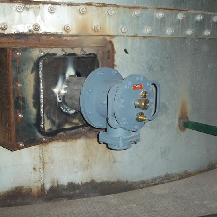
This is an MHF burner that is designed specifically for multiple hearth furnaces. The combustion air and natural gas piping have not been installed at this point.
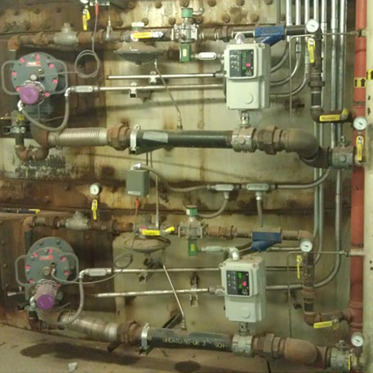
These are two MHF burner train assemblies that are specifically designed for multiple hearth furnaces. Individual natural gas lines are shown above each burner, while combustion air lines are shown below each burner.
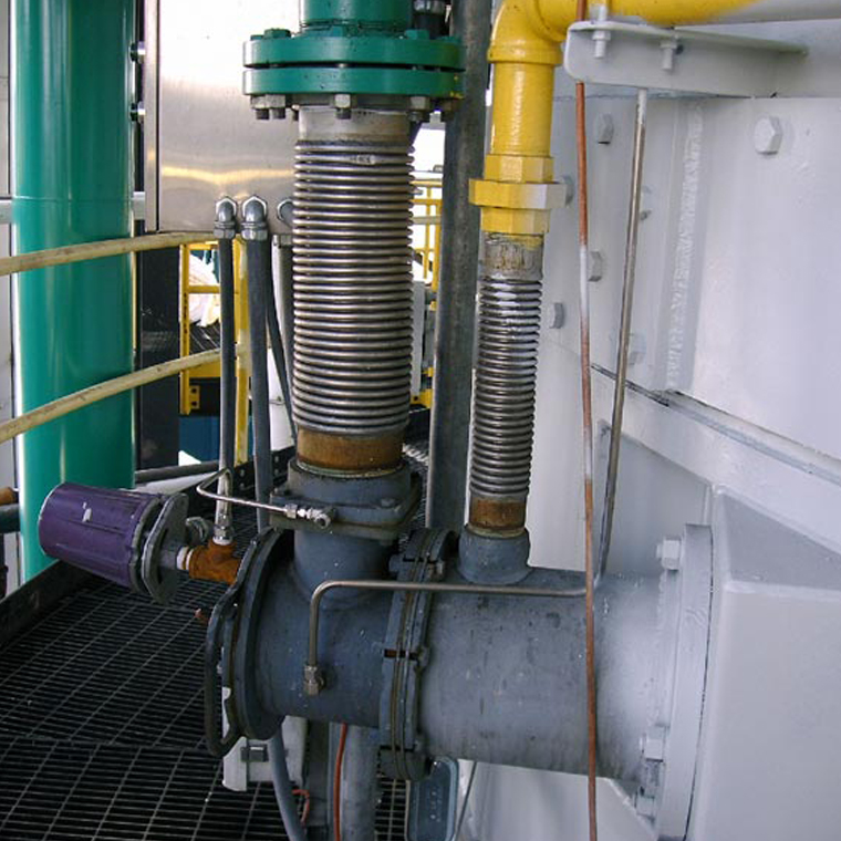
This is a MHF burner that is specifically designed for multiple hearth furnaces. The green line is the combustion air, while the yellow line is the natural gas. The purple instrument is the flame scanner that detects whether or not flame is present for safety precautions.
-

-

-

-

‹›
< back to main image
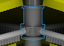
The centershaft holds the rabble arms and provides the motive force to move the material through the furnace. The centershaft generally spins at around one rpm. The centershaft assembly consists of several shaft sections, each of which holds the arms for one or two hearths. Most centershafts are air cooled, usually with an inner and an outer tube, or with interior baffles that direct the air into the arms and up along the shaft to the discharge point. Industrial Furnace can supply centershaft sections or entirely new centershaft assemblies on any furnace.
Click on the thumbnails below for additional information
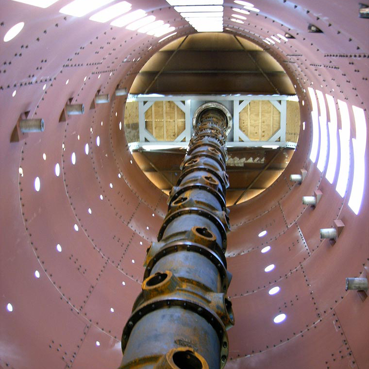
This is a centershaft installed in a multiple hearth furnace that is under construction. This picture was taken from the floor of the multiple hearth furnace looking up to the roof before the refractory installation had begun.
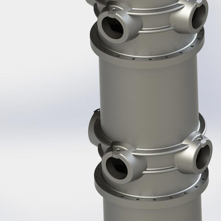
This is a 3D rendered image of a centershaft section. Shown in the image are the arm sockets for the rabble arms, as well as a partial view of the next centershaft section that sits on top.
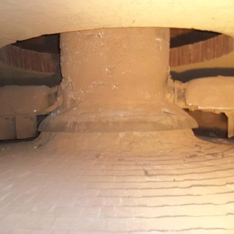
This is an image of a centershaft from a furnace in use. This particular centershaft is refractory lined in order to protect it from the high temperatures used in this particular application.
-

-

-

-

‹›
< back to main image
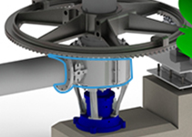
The centershaft and rabble arms use ambient air to cool and protect them. This air is fed by a centershaft cooling air fan. The air is introduced to the centershaft through the cooling air housing. Originally, the cooling air housings were cast iron. Industrial Furnace can still supply cast iron housings, however, we typically replace them with more durable fabricated steel housings if the original is damaged. We can supply custom fabricated steel cooling air housings for any MHF, from any manufacturer.
Click on the thumbnails below for additional information
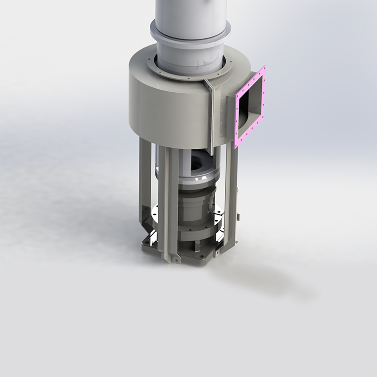
This is a 3D rendered image of a cooling air housing. The housing surrounds the lower part of the centershaft, where air enters through the inlets in the lower centershaft section and travels up through the centershaft to keep it cool.
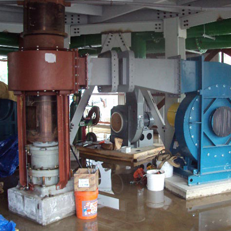
This image is taken underneath a multiple hearth furnace during construction, and shows the cooling air fan connected to the cooling air housing. The air travels into the housing through the inlets in the lower centershaft section, and travels up through the centershaft to keep it cool.
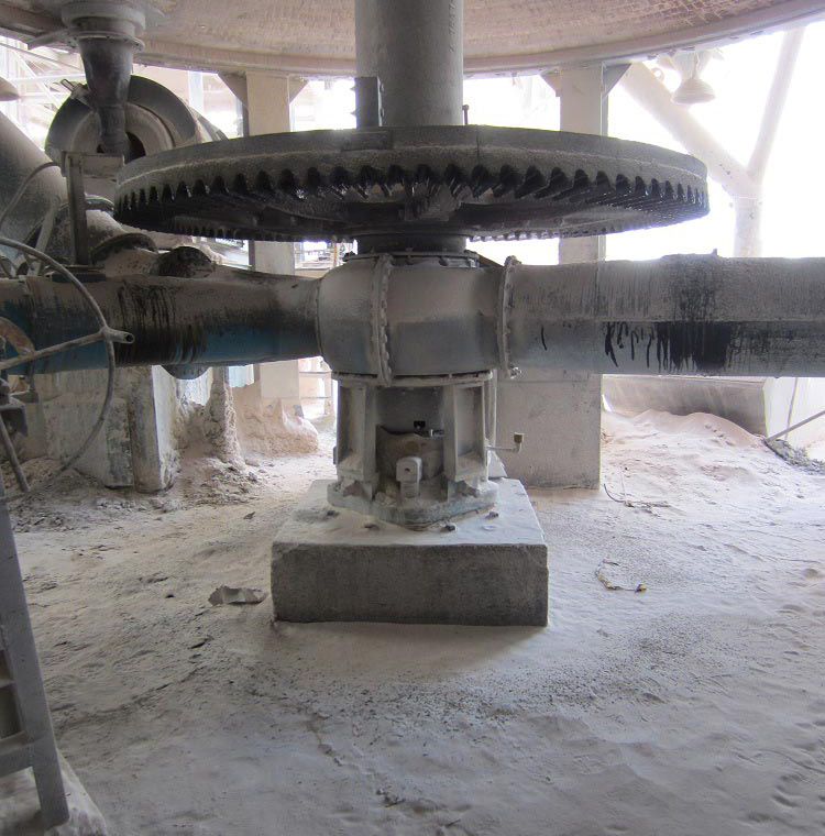
This is a cooling air housing in use on a multiple hearth furnace. The air travels into the housing through the inlets in the lower centershaft section, and travels up through the centershaft to keep it cool.
-

-

-

-

‹›
< back to main image
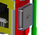
Industrial Furnace can supply cast or fabricated doors, complete door assemblies, or components to work with your existing furnace. We can supply doors to work with any diameter shell, in any of the common sizes.
Click on the thumbnails below for additional information
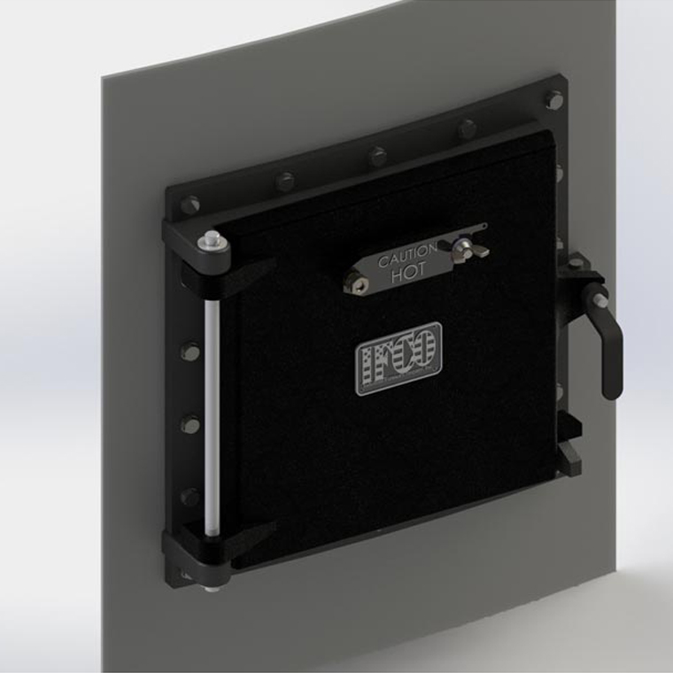
This is a 3D rendered image of a multiple hearth furnace door. Most doors have a radius on the flange to fit the shell of the multiple hearth furnace, and are refractory lined for durability and insulation purposes.
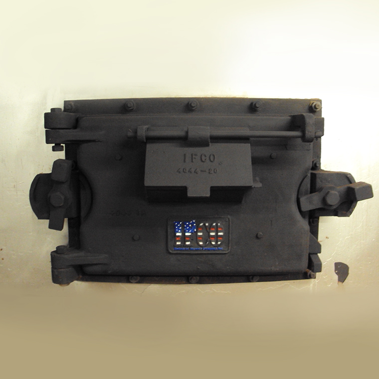
This is a picture of a multiple hearth furnace door. Most doors have a radius on the flange to fit the shell of the multiple hearth furnace, and are refractory lined for durability and insulation purposes.
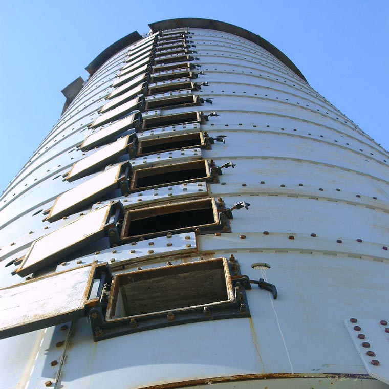
This is a picture of the doors on a multiple hearth furnace. Most doors have a radius on the flange to fit the shell of the multiple hearth furnace, and are refractory lined for durability and insulation purposes.
-

-

-

-

‹›
< back to main image
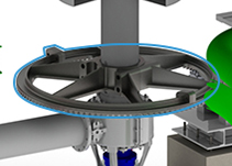
The centershaft is typically driven by a master gear and pinion gear combination, powered by a motorized gear reducer. Most furnaces utilize a tapered bevel design, in which the axis of the pinion and the axis of the master gear are perpendicular. Some furnaces use a spur gear arrangement, in which the pinion and master gear axis are parallel. Industrial Furnace can supply gears for any MHF. We can supply gears as cast, or machined, for both spur and tapered bevel gear styles.
Click on the thumbnails below for additional information
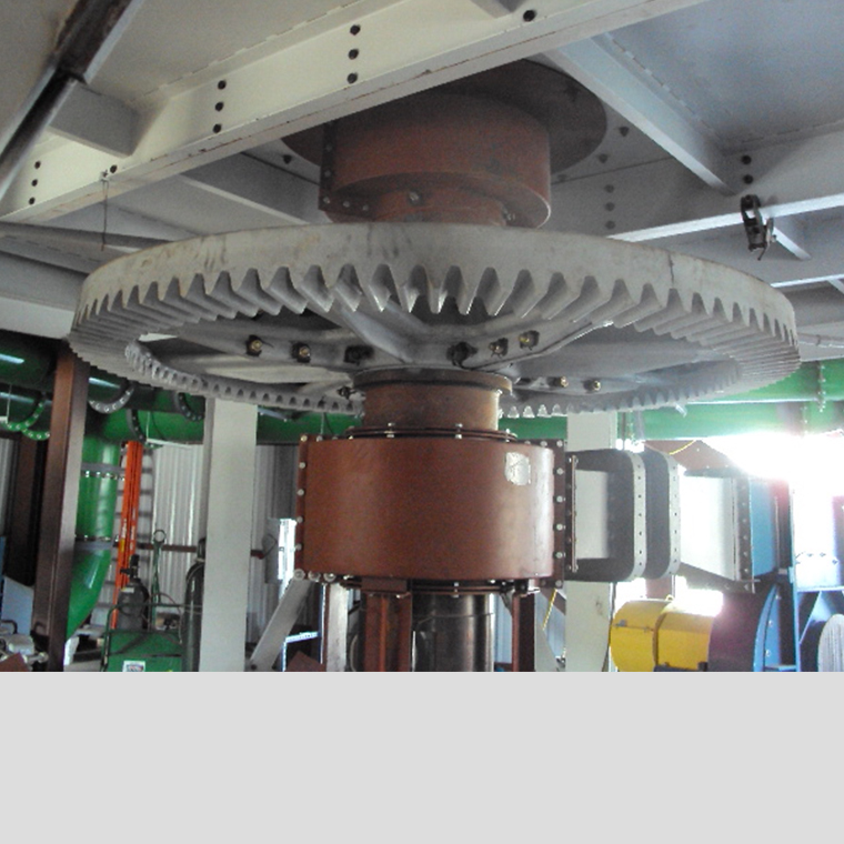
This is a master gear during construction of a multiple hearth furnace. The master gear is connected to the centershaft, and is driven by the pinion gear, which turns the centershaft of the furnace.
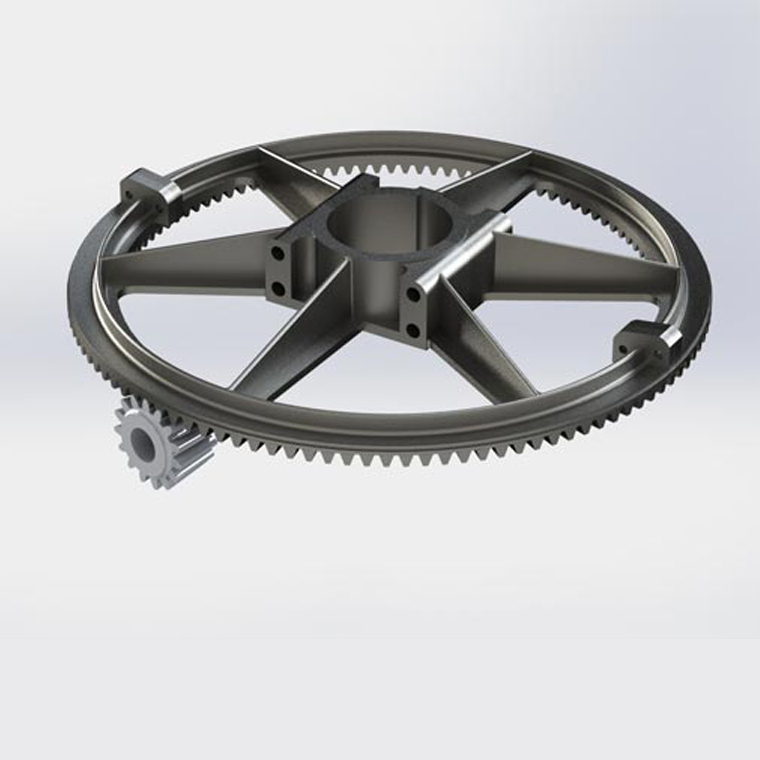
This is a 3D rendered image of a master gear and pinion gear. The master gear is connected to the centershaft, and is driven by a pinion gear, which turns the centershaft of the furnace.
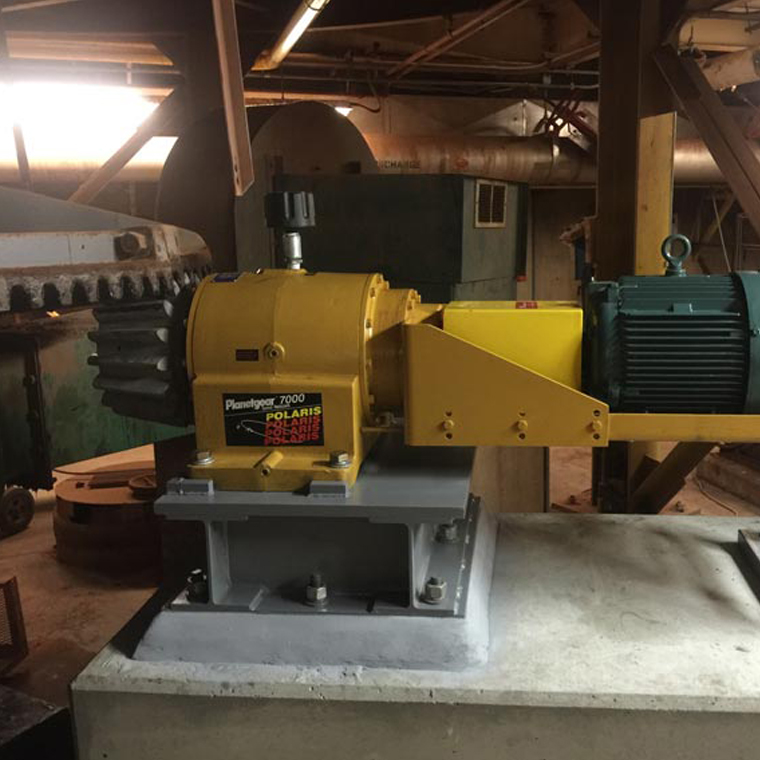
This is a pinion gear that drives the master gear of a multiple hearth furnace. The master gear is connected to the centershaft, which is rotated with the master gear.
-

-

-

-

‹›
< back to main image
The hearths are where the material is processed. The hearth consists of refractory brick and/or special shapes. Hearths in multiple hearth furnaces are self-supporting. They are generally “sprung arches,” but domes are not uncommon. The pitch of the hearth directs its weight outward to the skew, which is then transferred to the shell of the furnace. Industrial Furnace’s refractory experts can repair and replace hearths in any furnace. If you are experiencing a short hearth life, we can help you find a better suited refractory for your hearth.
Click on the thumbnails below for additional information
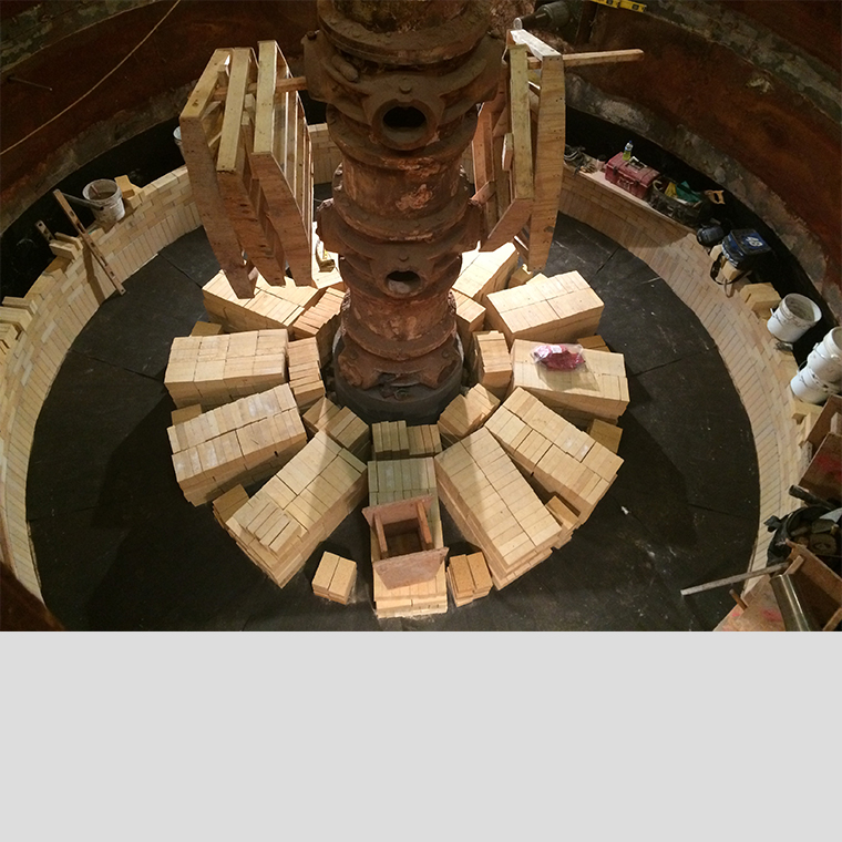
This is a hearth being installed on an existing multiple hearth furnance. This image shows the ring of skews installed, and the brick staged for the hearth installation.
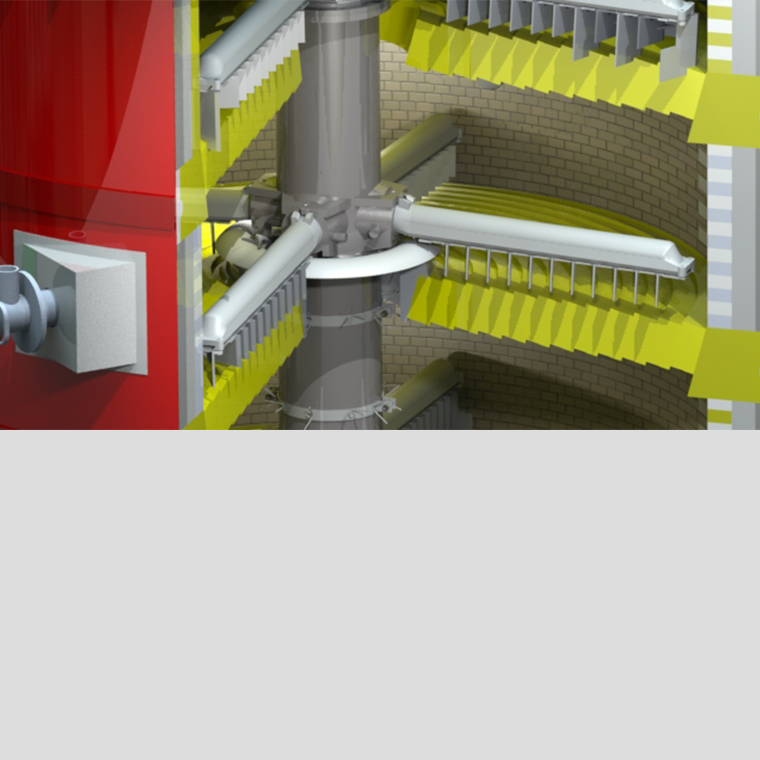
This is a 3D rendered image of a multiple hearth furnace. This three-quarter section view shows the two hearths stacked on top of each other, along with the rabble arms and teeth.
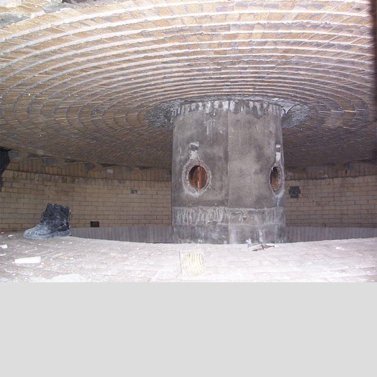
This is an image of a hearth on a multiple hearth furnace. This particular hearth is an “in hearth,” as it has one large hole in the center of the hearth. You can see the drop holes along the periphery of the “out-hearth” above this one.
-

-

-

-

‹›
< back to main image
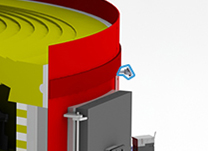
If the combustion system is the heart of the multiple hearth furnace, the Instrumentation and Controls (I&C) are the central nervous system. Industrial Furnace’s advanced I&C can ensure your furnace runs smoothly and safely. Our I&C experts can retrofit your existing furnace with a state-of-the-art control system, maximizing efficiency, and minimizing temperature and emissions excursions.
Click on the thumbnails below for additional information
.jpg)
Differential pressure transmitters are often used on MHF off-gas systems to measure pressure drop.
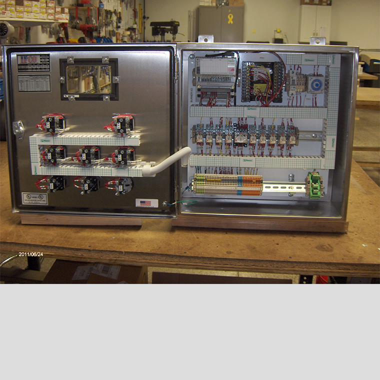
The internals of a burner control panel made in IFCO’s panel shop.
.jpg)
The type k thermocouple installed on the shell of a multiple hearth furnace. Typically at least one thermocouple is installed on every hearth.
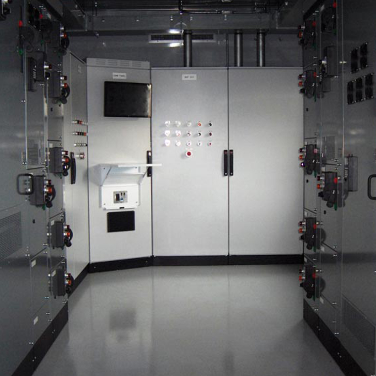
A control room designed and built by IFCO. The entire control room was constructed at IFCO’s headquarters, and shipped complete to the job site.
-

-
.jpg)
-

-
.jpg)
-

‹›
< back to main image
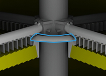
Lute caps are used on out-hearths to prevent material from “short circuiting” and dropping through the opening between a hearth and the centershaft. The lower lute cap prevents material from leaving the furnace or dropping into the bottom seal. Industrial Furnace makes lute caps to fit any MHF regardless of the manufacturer. Improvements such as the “clamp-on” lute cap, and increased overlap in the segments allows our lute caps to seal better than other manufacturers’ OEM parts.
Click on the thumbnails below for additional information
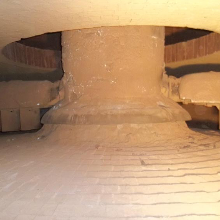
A lute cap installed on an MHF centershaft on an “out hearth.” The material beneath the curved lute cap is actually a hand-formed castable nose tile. Together, the lute cap and nose tile prevent material from dropping down around the centershaft.
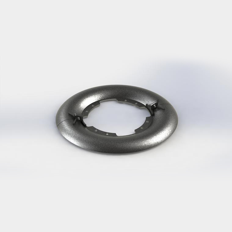
A 3D render of a typical lute cap. The two pieces bolt to each other and to the centershaft.
-

-

-

‹›
< back to main image
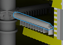
Rabble arms hold the rabble teeth. The arms are connected to the centershaft, and are cooled with the centershaft cooling air. The arms have a tube, rib, or ribs to direct the cooling air along the outside of the arm, and back to the centershaft. Industrial Furnace’s arms are heavier than our competitors, with thicker walls to increase the arm strength and durability. Industrial Furnace can supply improved arms for any MHF regardless of the original manufacturer.
Click on the thumbnails below for additional information
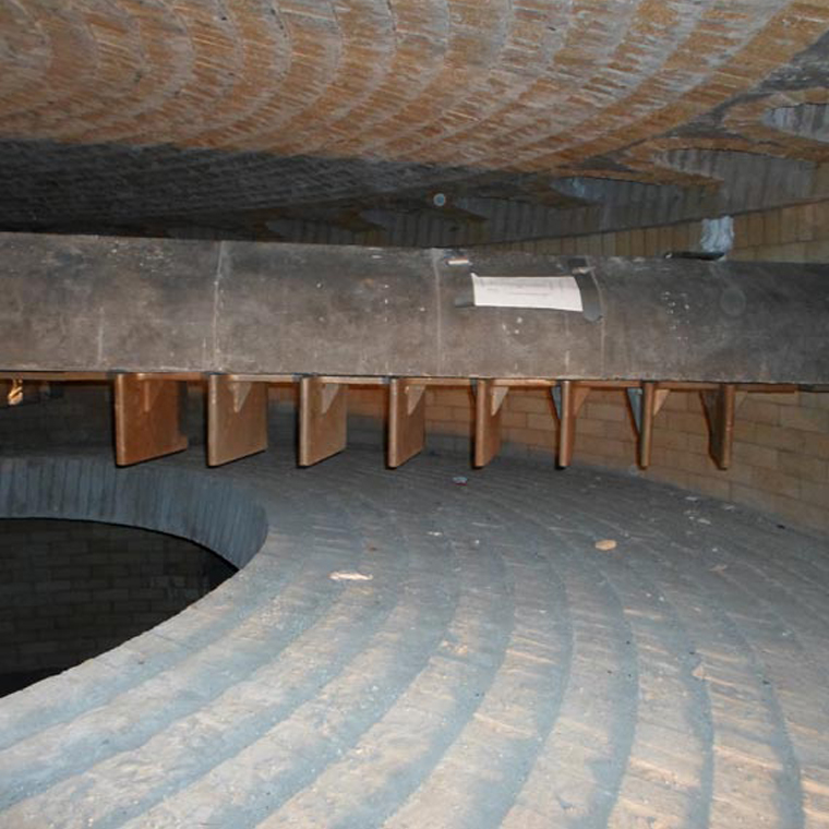
A new rabble arm installed in a newly constructed multiple hearth furnace. The arm itself is covered with castable refractory. Attached to the arm is a drawing that IFCO's inspectors use to verify the rabble pattern on each arm is correct.
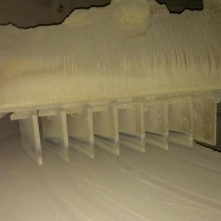
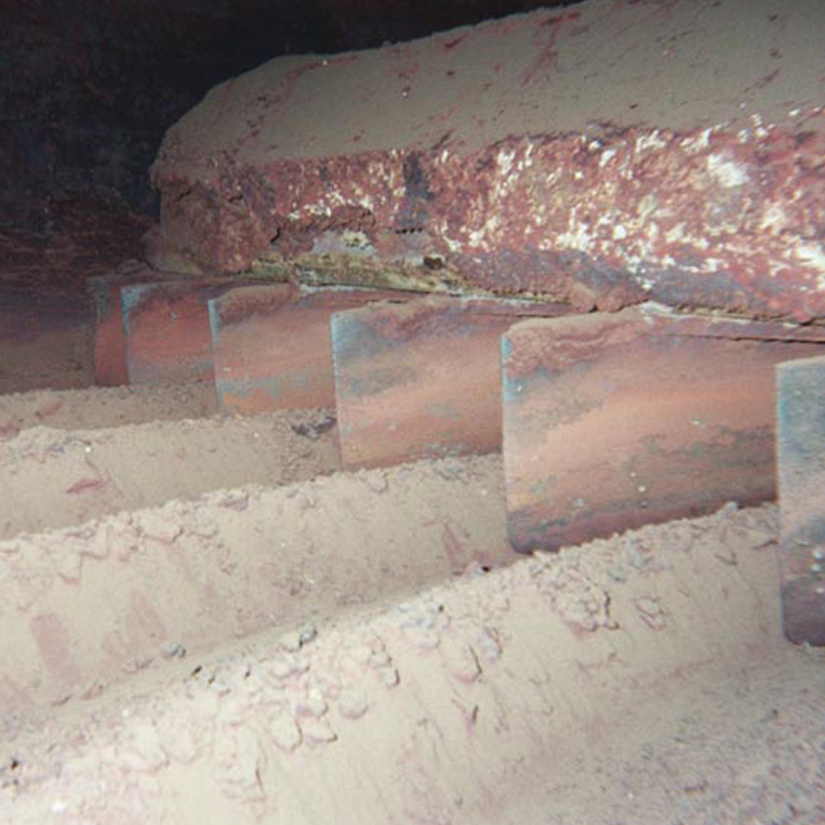
A rabble arm in operation. It is common for material to build up on top of arms as it falls from the hearth above.
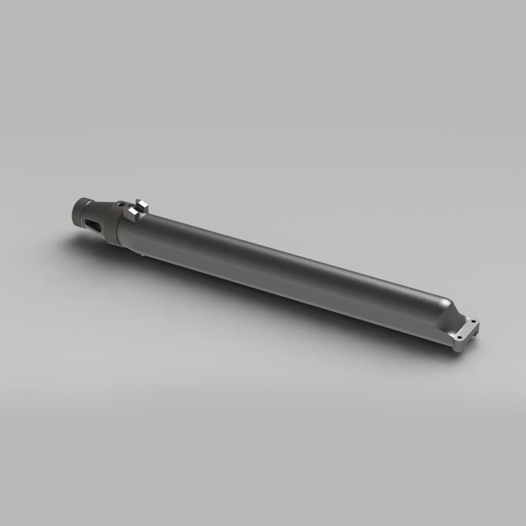
A 3D render of a typical rabble arm (without refractory insulation). These arms are air cooled, with one of the oblong air exit openings visible on the left side. The two machined rings on the left side fit tightly into matching sockets on the centershaft. The dovetail track on the bottom holds the rabble teeth.
-

-

-

-

‹›
< back to main image
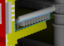
Rabble teeth stir and move the material through the furnace. They act like plows cutting furrows through the bed. Each furrow moves the material a little closer to the drop hole, as well as exposes fresh material to the furnace atmosphere. The teeth are generally made of cast stainless, though other materials are available. Industrial Furnace makes teeth for any size furnace, as well as furnaces made by other manufacturers. Our replacement rabble teeth are designed to fit perfectly, and provide long service life.
Click on the thumbnails below for additional information
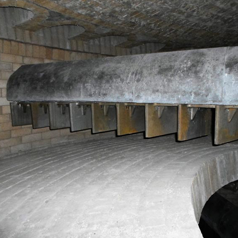
The teeth sit in the dovetail track at the bottom of the arm, and can be removed and replaced from the doors without removing the arm from the centershaft.
One row of teeth creates furrows in the bed. The teeth on the next arm will push these furrows a little further in or out depending on the type of hearth.
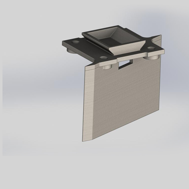
A 3D render of a typical rabble tooth. Nearly all teeth share a similar design. But the length and depth of the tooth blade, as well as the blade's position on the base can have large effects on how the tooth performs. Rabble patterns are designed carefully to ensure that the product is moved to the next hearth in the correct amount of time, with optimal turnover of the material.
-

-

-

-

‹›
< back to main image
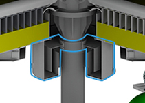
Multiple hearth furnaces utilize sand or water seals where the shaft penetrates through the top and bottom of the furnace. This keeps un-regulated air out of the system, as well as keeping ash, gasses, and material in the furnace. Depending on the application, the seals may be filled with sand, water, steel or stainless steel shot, or even crushed refractory. The seal bodies can be cast, or fabricated. Industrial Furnace can supply water or sand seals for any MHF, in either cast or fabricated materials. We regularly supply customers with stainless, cast iron, or fabricated steel seals.
Click on the thumbnails below for additional information
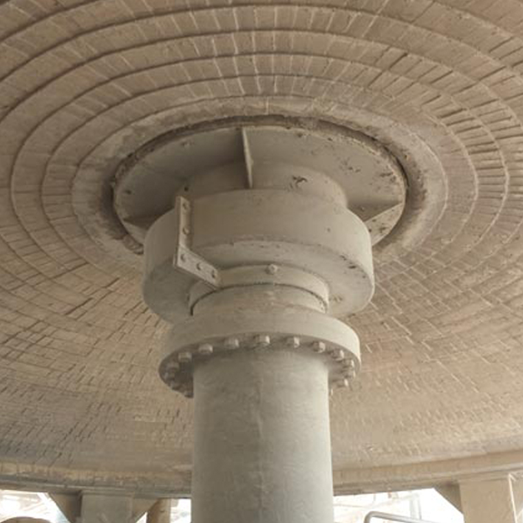
This lower sand seal is installed on an older style MHF with a brick floor. The outer trough bolts together around the spinning centershaft and uses sand as the sealing medium. The cap is fixed to the floor and consists of a stationary ring that is embedded in the sand. This seals the furnace atmosphere from the outside atmosphere while allowing the centershaft to spin freely.
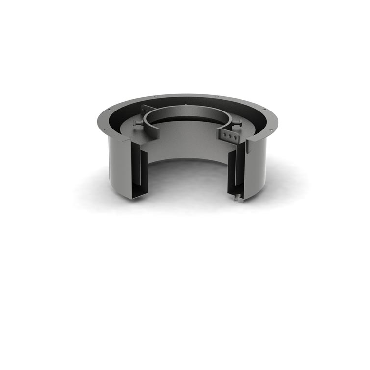
A 3D rendered section view of a lower water seal. The trough is fixed to the MHF floor and remains stationary, while the inner cap is fixed to the spinning centershaft. One of the water inlets is visible on the lower right-hand side.
-

-

-

‹›
< back to main image
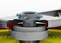
The top bearing supports the top of the centershaft, and keeps it plumb. The top bearing is generally a solid casting, with options for grease, oil, graphite, or oil impregnated bronze blocks. Some furnaces use roller bearings, or bronze sleeves on the top as well. Industrial Furnace can supply top bearings, and top bearing parts for any furnace. We can also engineer solutions to change from one design to another.
Click on the thumbnails below for additional information
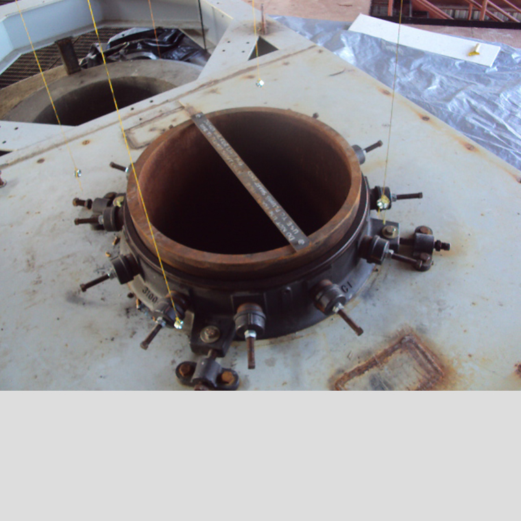
A top bearing installed on the top frame of an MHF. The lightly rusted top of the centershaft protrudes above the top of the bearing assembly. Three of the four adjusting screw assemblies can be seen. These are used in conjunction with a plumb bob during installation to ensure that the centershaft is plumb and level.
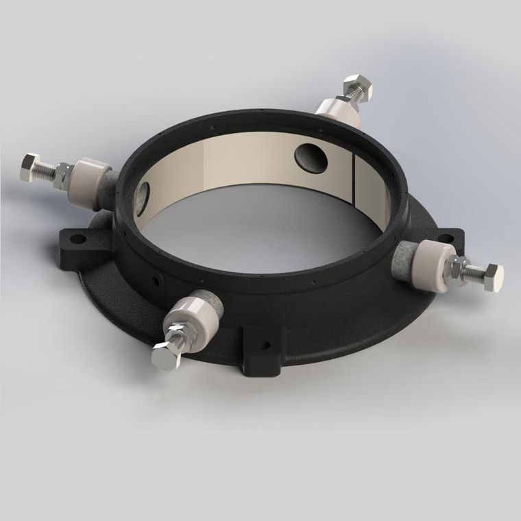
A 3D render of a top bearing. This model only has four graphite wear block assemblies, but other models can have more. These wear blocks prevent the centershaft from rubbing and damaging the bearing housing, though this can still happen if the adjustment screws are not tightened periodically to account for block wear.
-

-

-

‹›
< back to main image
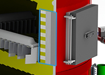
The shell of the MHF is typically steel plate rolled to a specific diameter. Skew bands are placed on the exterior of the shell where hearth skews are located. The skew bands contain the forces exerted outward from the hearths. The walls of the furnace have a refractory lining. The lining is engineered based on the process, but typically consists of one or two layers of insulation, with a hard brick face at the furnace interior. Industrial Furnace engineers the walls to withstand not only the temperature of the furnace, but also any chemical reactions within the hearth area. Industrial Furnace can repair walls and shells on any furnace. Our skilled crews can perform the refractory work required, as well as welding shell patches.
Click on the thumbnails below for additional information
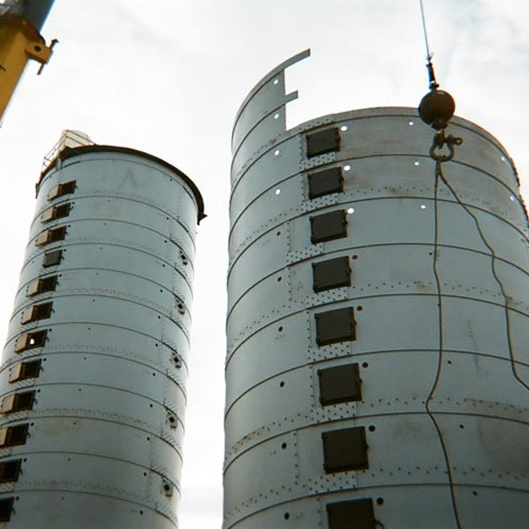
One completed and one partially completed shell. Rolled shell plate segments usually span one or two hearths. Note how the vertical splice plates are staggered for extra shell strength. Since the brick hearths are self-supporting, they exert force outward towards the shell. The thicker horizontal bands (skew bands) reinforce the shell at each hearth and prevent the rolled shell plates from deforming outward under that force.
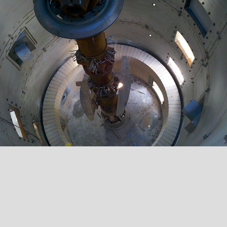
The interior of the shell before the walls and hearths are completed.
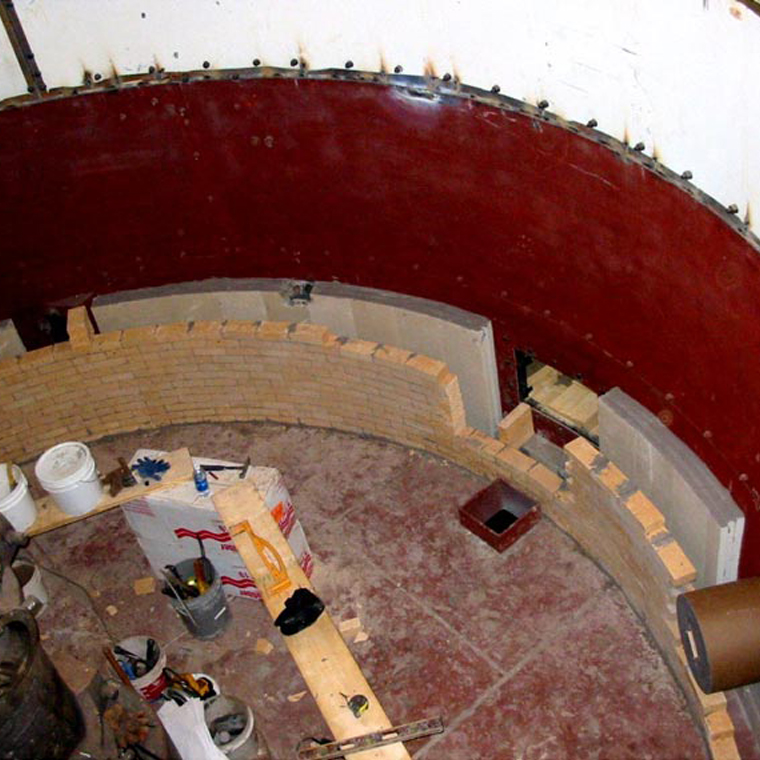
Furnace walls under construction. The different layers of material are clearly visible: Brick on the hot-face for resilience, and layers of mineral fiber board for insulation. Depending on the operating temperatures of the furnace, the walls can be made from different materials.
-

-

-

-

‹›
< back to main image


.jpg)

.jpg)


